
The power supply of the 11/70 is quite a beast, and we expect to spend some time to ensure it is working properly.
The entire power system is described in detail in chapter 4 of PDP-11/70 maintenance and installation manual (EK-11070-MM)

The power to the CPU goes through three stages in the processor cabinet. First through the 861-E power controller, then through the two H7420 power supplies, each containing four H744 +5V power regulators, before finally connecting through a cable harness to the CPU backplane and the front panel.

In addition, there are two 5411086 modules, one in each H7420. One provides +8V and +15V as well as a line clock. The other one provides -15V.

The physical locations for each regulator can be found in the table below.

861-E Power Controller
The power control unit is controlling and distributing power to all parts of the system, possibly through other power control boxes in other racks. It is a fairly simple device, as seen from the schematic below.
The 861-E is intended for 180-264V (312-458V phase to phase), while the 861-D version is for 90-132V (156-229V phase to phase).


The capacitance was measured from each phase (and neutral) to ground in the power connector to check the capacitors in the line filter. In these measurements, some capacitance was probably added from the long power cable. The capacitors across the switched outputs were also measured (C1 and C2 in the schematic above). Specified and measured values are listed in the table below.
| Capacitor location | Specified | Measured | Vloss |
| Line filter, phase 1 | 30nF | 51nF | 0.3% |
| Line filter, phase 2 | 30nF | 47nF | 0.3% |
| Line filter, phase 3 | 30nF | 47nF | 0.3% |
| Line filter, neutral | 30nF | 47nF | 0.3% |
| Output, phase 1 | 100nF | 106nF | 0.1% |
| Output, phase 2 | 100nF | 107nF | 0.1% |
| Output, phase 3 | 100nF | 100nF | 0.1% |
When taking the power controller out of the CPU cabinet, the 3 phase plug had to be removed. It looked like it had been running quite hot, and the isolation on the cables near the plug was brittle. 10-15 cm of the cable was cut off before the plug was mounted.


Everything now looks fine in the power controller, but we are not able to fully test it until we have access to a 230V three phase outlet, i.e. 400V between phases (not commonly available in Norwegian domestic buildings).

At least as a temporary solution, we should build converter cables from the NEMA 6-15R 250V plugs (see above) to the European style plug to connect the power supplies directly to mains instead of through the 861-E. A couple of these should work: https://no.mouser.com/ProductDetail/Qualtek/Q-722-BW?qs=BXmE%252BJ0Y7xam28jusjp7Eg==
H7420 Power Supply
This is the big and heavy part! It contains a massive transformer, up to five regulators and four 240V fans. Each +5V regulator will be removed and tested separately.

In the main body we find the transformer and the 5411086 regulator and monitor board. They are described on page 4-51 in EK11-11070-MM.
H744 Regulator
The H744 regulator is the component that in our experience fails most frequently. Each regulator must be tested on the bench.

Page 4-59 in EK-11070-MM describes the H744 regulators and on page 4-87 there are suggestions on how to diagnose a faulty regulator.
Schematics can be found here:
http://www.bitsavers.org/pdf/dec/pdp11/1170/EY-D3054-HO-002_45-70hw.pdf
http://dustyoldcomputers.com/pdp-common/reference/drawings/modules/h/h744.pdf
Each H744 regulator was tested separately in a setup similar to Figure 4-56 in the EK-1070-MM document (see below). The variac was adjusted slowly to increase the AC input voltage to the regulator to approximately 25V. A Python program was developed to control the electronic load (HP 6060B) and DMM (Fluke 45) over GPIB to gradually increase the output current from 0 to 20 A and measure the voltage.


To our surprise, all 7 regulators worked flawlessly. The output voltage was adjusted to 5.1V at 10A, but this may need to be adjusted again once the regulators are re-inserted into the cabinet and any voltage drop in the wire harness can be accounted for.

The regulated output waveform was similar to the one depicted in the maintenance manual. Some spikes should be expected according to the experts.


The only components that needed to be replaced were the light bulbs, which were obviously burnt out after many years of service. Instead of replacing with LEDs, 5 V light bulbs were used to give the authentic glow.

All H744 regulators are now tested and ready to be re-installed in the power supplies.

Wire harness
The whole power system is tied together with a rather impressive wire loom which connects to the CPU backplane. We will inspect it for damage as the cables might have dried out or got pinched.

Backplane
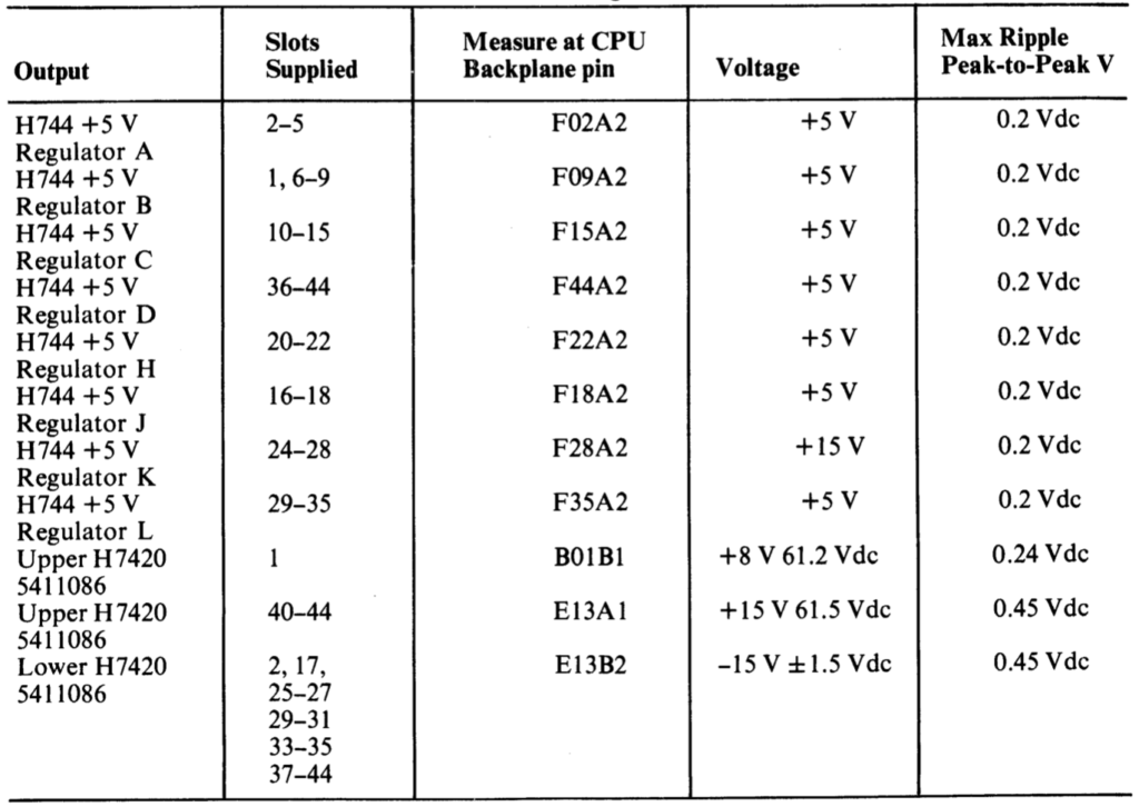
The last endevour in making sure the power supply is working properly means taking out all of the cards in the card cage and inspect for debris and damage. At this stage we can connect the power supply to the backplane and turn the power on. EK-11070-MM lists test points on the backplane were we will double check voltages before beginning to populate the system with cards and move on to testing the CPU.
The expected voltages at the backplane can be found in the table below.
The card chassi contains ten(10!) 240V fans that we should take the oportunity to test and maybe service.